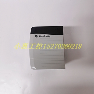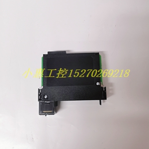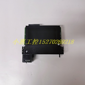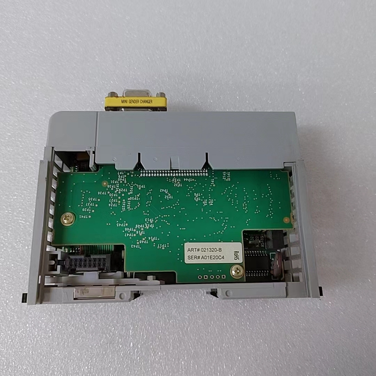
1391-DES15-DI-AQB扩展驱动模块
类目:A-B
型号:1391-DES15-DI-AQB
全国服务热线:+86 15270269218
手机:+86 15270269218
微信:+86 15270269218
QQ:3136378118
Email:stodcdcs@gmail.com