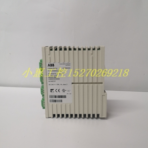
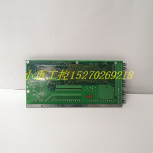
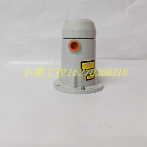
【主营产品】prefix = "o" ns = "urn:schemas-microsoft-com:office:office"
主营:世界知名品牌的PLC、DCS系统备件 模块
①Allen-Bradley(美国AB)系列产品》
②Schneider(施耐德电气)系列产品》
③General electric(通用电气)系列产品》
④Westinghouse(美国西屋)系列产品》
⑤SIEMENS(西门子系列产品)》
⑥销售ABB Robots. FANUC Robots、YASKAWA Robots、KUKA Robots、
Mitsubishi Robots、OTC Robots、Panasonic Robots、MOTOMAN
Robots。
⑦estinghouse(西屋): OVATION系统、WDPF系统、MAX1000系统备件
。
⑧Invensys Foxboro(福克斯波罗):I/A Series系统,FBM(现场输入
/输出模块)顺序控制、梯形 逻辑控制、事故追忆处理、数模转换、输入/
输出信号处理、数据通信及处理等。Invensys Triconex: 冗余容错控制
系统、基于三重模件冗余(TMR)结构的zui现代化的容错控制器。
⑨Siemens(西门子):Siemens MOORE, Siemens Simatic C1,Siemens
数控系统等。
⑩Bosch Rexroth(博世力士乐):Indramat,I/O模块,PLC控制器,驱动
模块等。
◆Motorola(摩托罗拉):MVME 162、MVME 167、MVME1772、MVME177等系列。
尊敬的顾客您好,为了更好的保障您的合法权益,购买前请仔细阅读以下内容:
1.价格说明 并非原价,请以询价为准。
价格说明 并非原价,请以询价为准。
价格说明 并非原价,请以询价为准。
2.由于市场波动频繁,本店所标价格,并非实价,请买家提前咨询 后再拍,感谢支持。
3.所售商品报价均为不含税价 ,如须开票,请和店主联系。
4.本店所售商品均为正品现货,图片实物拍摄。如果您订购产品超过 多件,请与我们联系,我们可以为您尽量提供折扣。
5本店产品分为全新原装、全新无包装,工程余货和二手四种货品。购买前请联系客服仔细核对货品、型号、数量。
6.本店所售商品保证质量,全新无包装和二手商品签收十五日出现问题均包退换,请放心购买。所有配件质保一年。因买家自己弄错产品型号、参数或剪脚、上机、错误接入电源、错误安装、保管不当、人为损坏等除外。
7.本店所售商品国内顺丰包邮,国外运费自理。支持十五天内有任何产品质量问题退换货,过期一切损失请自行承担。请大家在货物签收时一定仔细检查物品外观是否完好无损,数量是否短缺,配件是否齐全如发现有任何问题请不要签收并立即致电我们,货物一旦签收完毕,就代表双方对货物外表、数量、配件一致认可无争议。
拍下商品后,视为认可以上各项条款,谢谢合作!
PLC ladder diagram programming language is a kind of programming language developed from relay contact control circuit diagram. The structure of the two languages is very similar, but there are essential differences in the process of program execution. Therefore, as the three basic elements of relay contact control system and ladder diagram, contact, coil and wiring are essentially different.
The "normally open" and "normally closed" contacts of input, output, internal relay and other programming elements used in ladder diagram are essentially the data "bit" status of a memory in PLC. The "normally open" contact in the program directly uses the state of this bit for logic operation“ Normally closed "contacts are processed using the" logical not "state of this bit. The difference between it and relay control circuit is that the contact in ladder diagram can be used infinitely in the program. Unlike physical relay, it is limited by the number of contacts actually installed. At any time, the state of the "normally open" and "normally closed" contacts in the ladder diagram is unique, and it is impossible for them to be "L" at the same time. There is a strict "not" relationship between the "normally open" and "normally closed" contacts.
Although the internal relay, output and other programming elements used in ladder diagram programming use the same name of "coil" as relay control circuit, they are not physical relays. The program controls the output of the above coils only by assigning the status of the data "bit" of a memory in PLC. The data "bit" setting "1" corresponds to the "power on" of the coil; Data "bit" set to "0" corresponds to "power off". Therefore, it differs from the relay control circuit in that if necessary, the "output coil" in the ladder diagram can be assigned multiple times in the program, that is, the so-called "repeating coil" can be used in the ladder diagram. The execution of PLC program strictly follows the sequence of ladder diagram "from top to bottom" and "from left to right". In the same PLC program execution cycle, the output state of executed command cannot be changed (the output state of executed command can only be changed in the next cycle). By effectively using this program execution characteristic of PLC, we can design many special logic different from relay control circuit, such as "edge" signal processing.
The "connection" in the ladder diagram only represents the processing sequence relationship of instructions in PLC ("from top to bottom", "from left to right"), it does not have the actual current as the relay control circuit, so each output coil in the ladder diagram should have its own independent logic control "circuit" (i.e. clear logic control relationship), The "bridge type connection" mode often used in relay control circuit can not be used between different output coils, trying to change the executed command output through the later execution conditions

