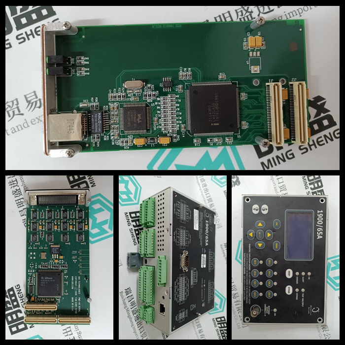
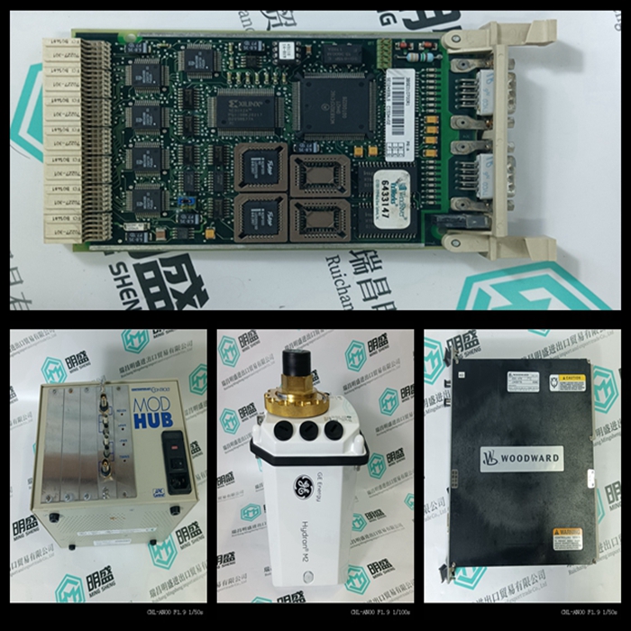
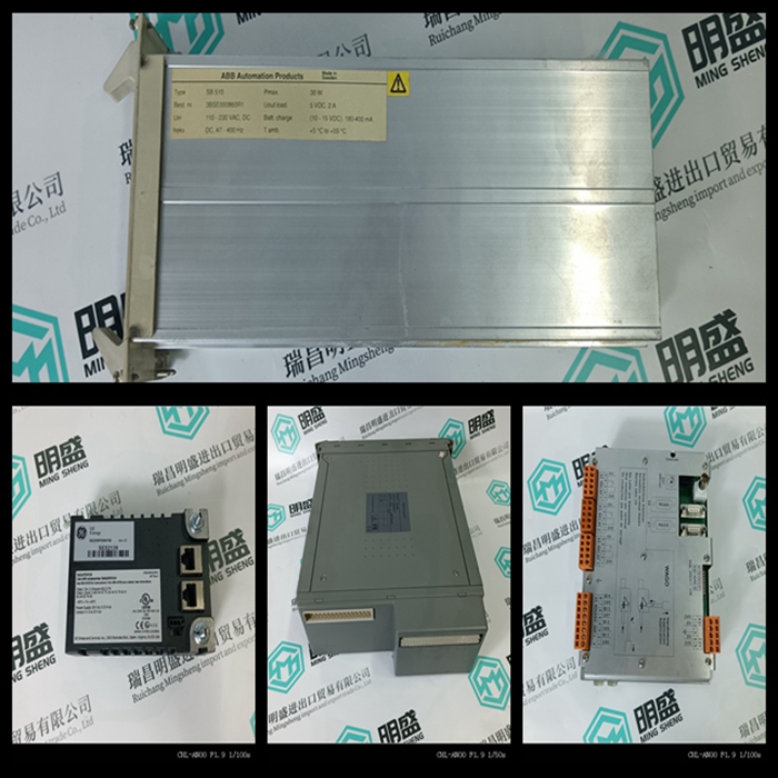
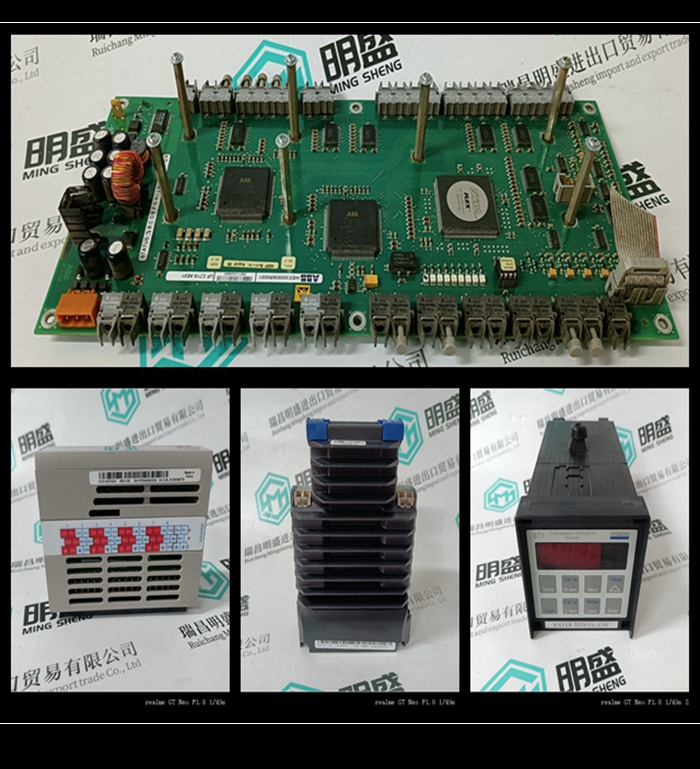
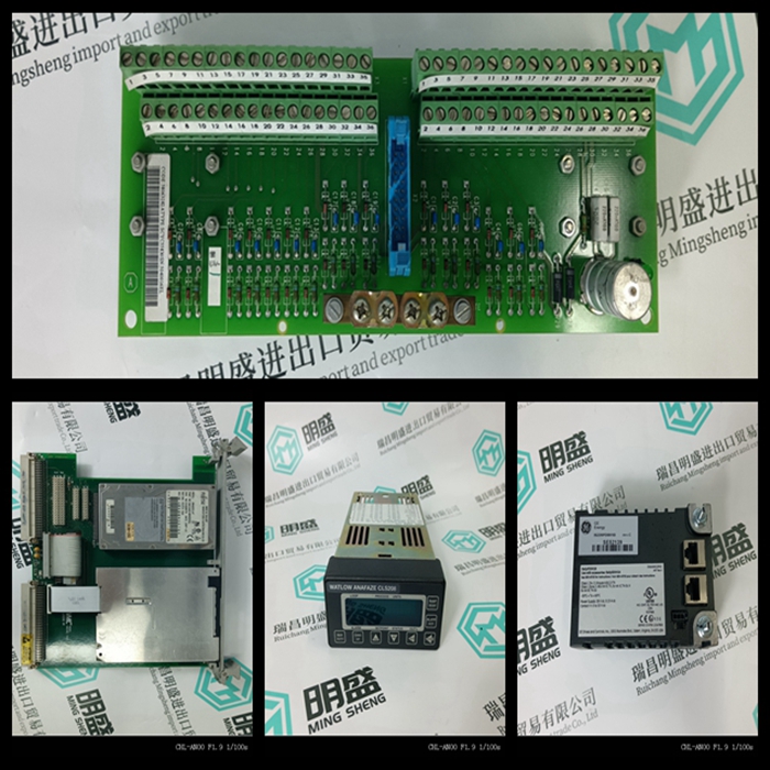
WOODWARD 8280-412扩展驱动模块库存
类目:WOODWARD伍德沃德
型号:WOODWARD 8280-412
全国服务热线:+86 15270269218
手机:+86 15270269218
微信:+86 15270269218
QQ:3136378118
Email:stodcdcs@gmail.com